Dimplex Electric Fireplace Manual: A Comprehensive Guide
Welcome to your comprehensive guide to understanding your Dimplex electric fireplace. This manual will provide you with valuable information on how to safely and effectively operate your Dimplex fireplace, ensuring years of warmth and ambiance. From safety precautions to troubleshooting tips, we’ve got you covered!
Dimplex is a leading manufacturer renowned for its innovative and high-quality electric fireplaces. Dimplex electric fireplaces offer a convenient and aesthetically pleasing alternative to traditional wood-burning or gas fireplaces. They provide the ambiance of a real fire without the associated hassles, such as chimney maintenance, wood storage, or gas line installation.
Dimplex fireplaces are designed with advanced technologies, including realistic flame effects and energy-efficient heating systems. These fireplaces utilize LED lighting to create the illusion of a flickering fire, offering a cozy and inviting atmosphere. Many models also incorporate features like adjustable flame brightness, temperature control, and remote operation for enhanced user convenience.
Dimplex offers a diverse range of electric fireplace styles to suit various preferences and home décor. From traditional mantel fireplaces to modern wall-mounted units, there’s a Dimplex fireplace to complement any living space. Whether you’re looking to add warmth to your living room, bedroom, or office, a Dimplex electric fireplace can provide a stylish and functional heating solution.
Importance of the User Manual
The user manual accompanying your Dimplex electric fireplace is a crucial resource that should not be overlooked. It serves as a comprehensive guide, providing essential information for the safe and proper operation of your appliance. Neglecting to consult the user manual can lead to incorrect installation, improper usage, and potential safety hazards.
The user manual contains vital safety instructions and warnings that are designed to protect you and your property. It outlines potential risks associated with the fireplace, such as electrical hazards or overheating, and provides guidance on how to mitigate these risks. By carefully reviewing these safety precautions, you can ensure a safe and enjoyable experience with your Dimplex fireplace.
Furthermore, the user manual offers detailed instructions on how to install and operate your fireplace correctly. It explains the various features and functions of the appliance, including how to adjust the flame settings, control the temperature, and use the remote control. By following these instructions, you can maximize the performance and longevity of your Dimplex fireplace.
Safety Information and Warnings

Your safety is paramount when operating any electrical appliance, and the Dimplex electric fireplace is no exception. This section highlights critical safety information and warnings that must be carefully adhered to in order to prevent personal injury, property damage, or fire hazards.
Always read the entire user manual before attempting to install or operate the fireplace. Familiarize yourself with all safety instructions and warnings. Never leave the fireplace unattended while in operation. Keep flammable materials, such as furniture, curtains, and paper, at least 3 feet away from the fireplace. Do not use the fireplace in damp or wet locations, such as bathrooms or laundry rooms.
Ensure that the fireplace is properly grounded and connected to a dedicated 15 AMP, 120 VOLT circuit. Never overload the electrical circuit. Inspect the power cord regularly for any signs of damage. If the cord is damaged, do not use the fireplace and contact a qualified electrician for repair or replacement.
Do not insert any objects into the fireplace openings. Do not attempt to modify or repair the fireplace yourself. Contact Dimplex customer service or a qualified technician for any repairs or maintenance.
Installation Instructions
Proper installation is crucial for the safe and efficient operation of your Dimplex electric fireplace. These instructions provide a step-by-step guide to ensure correct installation, whether you’re integrating it into an existing fireplace opening, new wall construction, or using a Dimplex mantel surround kit.
Before you begin, carefully unpack the fireplace and inspect it for any damage. Ensure you have all the necessary tools and materials, including a screwdriver, level, and measuring tape. Select a suitable location that is not susceptible to moisture and is away from drapes, furniture, and high traffic areas.
For existing fireplace openings, ensure the opening is clean and free of any obstructions. For new wall construction, frame the opening according to the dimensions specified in the manual. If using a Dimplex mantel surround kit, follow the instructions provided with the kit.
Carefully lift the fireplace and insert it into the opening. Use a level to ensure the fireplace is properly aligned. Secure the fireplace to the wall or mantel using the provided mounting brackets and screws. Ensure all electrical connections are properly made and comply with local building codes. Once installed, carefully conceal the power cord to prevent tripping hazards.
Operating Instructions
Now that your Dimplex electric fireplace is properly installed, let’s get it up and running! These operating instructions will guide you through the basic functions and features of your fireplace, ensuring a cozy and enjoyable experience.
First, locate the main power switch; This switch typically supplies power to all fireplace functions, including the heater and flame effect. Turn the main power switch ON to activate the fireplace. Next, adjust the flame action control knob to your desired flame speed. Experiment with different settings to find the perfect ambiance.
If your fireplace has an interior light control, you can adjust the brightness of the interior lights to further customize the look and feel. To activate the heater, locate the heater control switch or button. Depending on your model, you may have multiple heat settings to choose from. Select the desired heat level and enjoy the added warmth.
For models with a remote control, refer to the “Remote Control Functionality” section for detailed instructions. Remember to always unplug the fireplace before performing any maintenance or cleaning. Enjoy the warmth and beauty of your Dimplex electric fireplace!
Understanding the Controls
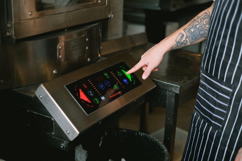
Familiarizing yourself with the controls of your Dimplex electric fireplace is crucial for optimal operation and enjoyment. The control panel, usually located on the front or side of the unit, houses various buttons, switches, and knobs that govern different functions of the fireplace; Let’s break down the common controls you’ll encounter.
The Main Power Switch: This is the master switch that turns the entire fireplace ON or OFF, supplying power to all other functions. Flame Control: Typically a knob or button, this adjusts the intensity and speed of the flame effect, allowing you to customize the visual ambiance. Heater Control: This controls the heating function, often with multiple settings (low, high, or thermostat-controlled) to regulate the amount of heat produced.
Temperature Adjustment: Some models feature a thermostat, allowing you to set a desired room temperature. The fireplace will then automatically cycle the heater ON and OFF to maintain that temperature. Light Control: Adjusts the brightness of the interior lights, enhancing the flame effect. Timer Function: Allows you to set a timer for the fireplace to automatically turn OFF after a specified duration, conserving energy. Understanding these controls empowers you to personalize your fireplace experience.
Remote Control Functionality
Many Dimplex electric fireplaces come equipped with a remote control, offering convenient operation from anywhere in the room. Understanding the functionality of your remote is key to maximizing its benefits. Typically, Dimplex remotes use radio frequency (RF) technology, meaning they don’t need to be pointed directly at the fireplace and can even work through walls within a certain range (usually around 50 feet).
Common remote functions include: Power ON/OFF: Turns the fireplace ON or OFF remotely. Flame Control: Adjusts the flame intensity and speed. Heater Control: Activates or deactivates the heater, and may also allow you to adjust the heat settings. Temperature Adjustment: If your fireplace has a thermostat, the remote can be used to set the desired room temperature.
Light Control: Adjusts the brightness of the interior lights. Timer Function: Sets a timer for the fireplace to automatically turn OFF. Some remotes may also have additional features like preset modes (e.g., “cozy mode,” “energy-saving mode”). Always refer to your specific model’s manual for a complete list of functions. Battery replacement instructions are also usually included in the manual. Enjoy the convenience!
Maintenance and Cleaning
Proper maintenance and cleaning are essential for keeping your Dimplex electric fireplace in optimal condition and ensuring its longevity. Before performing any maintenance, always disconnect the power supply to reduce the risk of electric shock or damage. Regular cleaning will help prevent dust buildup and maintain the fireplace’s aesthetic appeal.
To clean the exterior, use a soft, damp cloth. Avoid using abrasive cleaners or solvents, as these can damage the finish. For the glass screen, use a glass cleaner specifically designed for fireplaces or a mixture of vinegar and water. Be careful when handling the glass, as it can break if bumped or dropped. Regularly inspect the air intake vents and remove any dust or debris that may be blocking them. This will ensure proper airflow and prevent overheating.
Depending on the model, you may also need to periodically clean the flame effect components. Refer to your user manual for specific instructions on how to do this. If you notice any unusual noises or malfunctions, contact Dimplex customer service for assistance. By following these simple maintenance tips, you can keep your Dimplex electric fireplace looking and functioning its best for years to come.
Light Bulb Replacement
The realistic flame effect in your Dimplex electric fireplace is often created by light bulbs, and occasionally these bulbs will need replacement. Before attempting any light bulb replacement, always disconnect the power supply and allow the bulbs to cool down for at least five minutes to prevent burns.
Refer to your Dimplex electric fireplace manual to identify the correct type and wattage of the replacement bulb. Using the wrong bulb can damage the unit or create a fire hazard. Once the unit is cool and unplugged, carefully remove the access panel or cover that protects the light bulb compartment. Gently unscrew the old bulb and replace it with the new one, ensuring it is securely tightened.

When replacing the bulb, it’s a good practice to replace all the bulbs at the same time, especially if they are close to the end of their rated life. This minimizes the need for frequent replacements. After replacing the bulb, reassemble the access panel or cover and ensure it is properly secured. Finally, reconnect the power supply and test the fireplace to ensure the new bulb is working correctly. If the new bulb doesn’t light, double-check the connections and consult the troubleshooting section of your manual.
Troubleshooting Common Issues
Even with proper care and maintenance, you may occasionally encounter issues with your Dimplex electric fireplace. Before contacting customer service, consult this troubleshooting guide to resolve common problems. If the fireplace doesn’t turn on, first ensure that the power cord is properly plugged into a functioning outlet and that the main power switch is in the “on” position.
If the flames are not working, check the light bulbs as they may need replacing. If the heater is not producing heat, verify that the heater function is enabled and that the thermostat is set to a desired temperature. Also, make sure that the air vents are not blocked by any obstructions.
If the remote control is not working, replace the batteries and ensure that there are no obstructions between the remote and the fireplace. If the issue persists, try re-pairing the remote with the fireplace following the instructions in the manual. In case of unusual noises or smells, immediately turn off the fireplace and contact Dimplex customer service for assistance. If you need to continuously reset the heater, unplug the unit and call your local dealer. Always refer to your Dimplex electric fireplace manual for more specific troubleshooting steps related to your model.
Warranty Information
Your Dimplex electric fireplace comes with a limited warranty, offering you peace of mind against manufacturing defects. The specific terms and duration of the warranty vary depending on the model, so please refer to the warranty card included with your purchase or visit the Dimplex website for detailed information. The warranty typically covers defects in materials and workmanship under normal use.
To make a warranty claim, you’ll generally need to provide proof of purchase, such as a receipt, along with a description of the issue. The warranty may not cover damages resulting from misuse, abuse, improper installation, unauthorized repairs, or normal wear and tear. Dimplex, at its discretion, will either repair or replace the defective product or part without charge.
If repair or replacement isn’t feasible, Dimplex may offer a refund of the purchase price. Please note that Dimplex is not liable for any indirect, special, or consequential damages. Keep your purchase documents safe and accessible; Always contact Dimplex customer service prior to initiating any repair work not explicitly covered by the warranty. Remember to register your product online to streamline any future warranty claims.
Contacting Dimplex Customer Service
Dimplex is committed to providing excellent customer service and support for your electric fireplace. Should you encounter any issues, have questions about your product, or require assistance with troubleshooting, their customer service team is readily available to help.
You can reach Dimplex customer service through several channels. The most direct method is often by phone. The toll-free number for Dimplex customer service is 1-888-DIMPLEX (1-888-346-7539). When calling, be sure to have your model and serial number ready, as this will help the representative assist you more efficiently. These numbers can be found on the rating plate of your fireplace, usually located inside the unit.
Alternatively, you can visit the Dimplex website, www.dimplex.com, where you’ll find a wealth of information, including FAQs, product manuals, and troubleshooting guides. The website also features a contact form that you can use to submit your inquiries in writing. When contacting Dimplex, please provide a detailed description of your issue and any relevant information about your fireplace. This allows them to address your concerns promptly and effectively. Their dedicated team is eager to help resolve any problems.
Available Dimplex Fireplace Models
Dimplex offers a wide array of electric fireplace models to suit diverse tastes and heating needs. From built-in linear fireplaces to traditional mantels and portable stoves, there’s a Dimplex fireplace for every space. Their innovative designs and realistic flame effects make them a popular choice for homeowners.
The IgniteXL series, including the Bold 50, 60, 74, 88, and 100 models (XLF5017-XD, XLF6017-XD, XLF7417-XD, XLF8817-XD, XLF10017-XD), feature a sleek, modern design with edge-to-edge glass and vibrant flame colors. These built-in linear fireplaces add a touch of sophistication to any room.
For those seeking a more traditional look, Dimplex offers models with classic mantel designs and realistic log sets. The Opti-myst series utilizes ultrasonic technology to create a convincing smoke and flame effect, adding warmth and ambiance to your living space. Dimplex also provides wall-mounted options, perfect for smaller rooms or apartments, saving space while still providing the cozy feel of a fireplace. Regardless of your preference, Dimplex has a model to complement your home decor.